How to Insulate Pipe Tees and Elbows in Shipbuilding & Marine Engineering
Pipeline insulation is a critical process for safety and operational efficiency in shipbuilding and marine engineering. Unlike onshore industrial pipelines, the marine environment is characterized by constant vibration, seawater corrosion and limited working space. Therefore, the insulation construction of pipe fittings, especially pipe tees and elbows, must comply with more stringent technical standards.
Core Construction Procedures
Step 1: Material Selection
Non-asbestos rockwool is recommended as the core material for marine pipeline insulation, matched with metal cladding. In accordance with ASTM F683 standard, the type and thickness of insulation materials shall be selected by referring to the temperature range table in marine specifications.
Insulation is mandatory for exhaust or high-temperature pipelines with surface temperature above 60℃, and the materials shall pass IMO A60 fire resistance certification. This rating requires the insulation system to maintain structural integrity for more than 120 minutes in case of fire. Rockwool insulation can withstand pipeline surface temperature up to 1400°F (760°C).
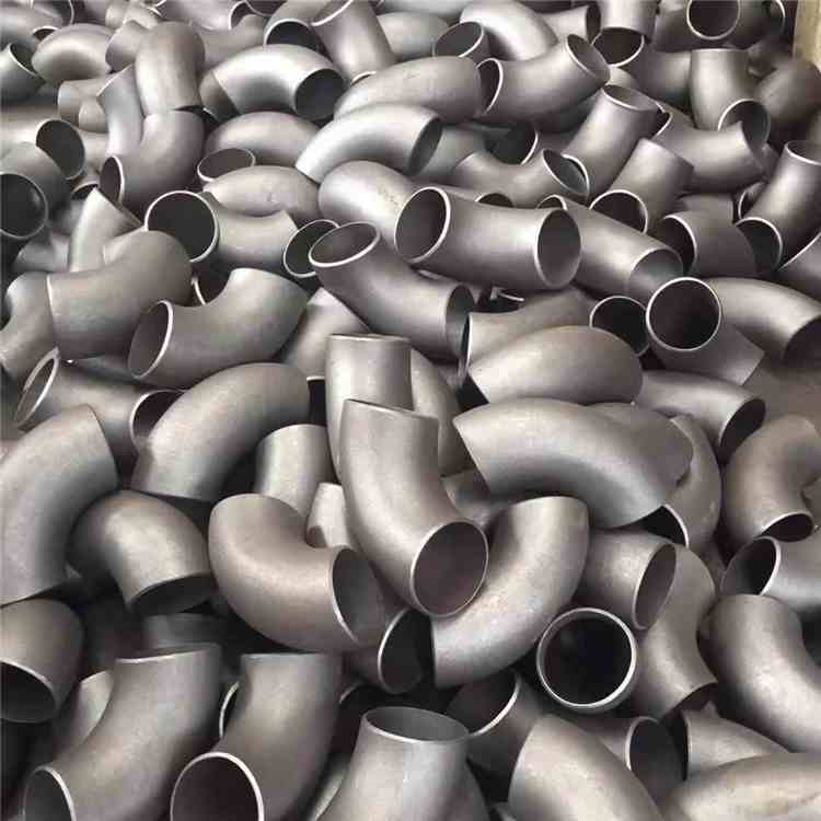
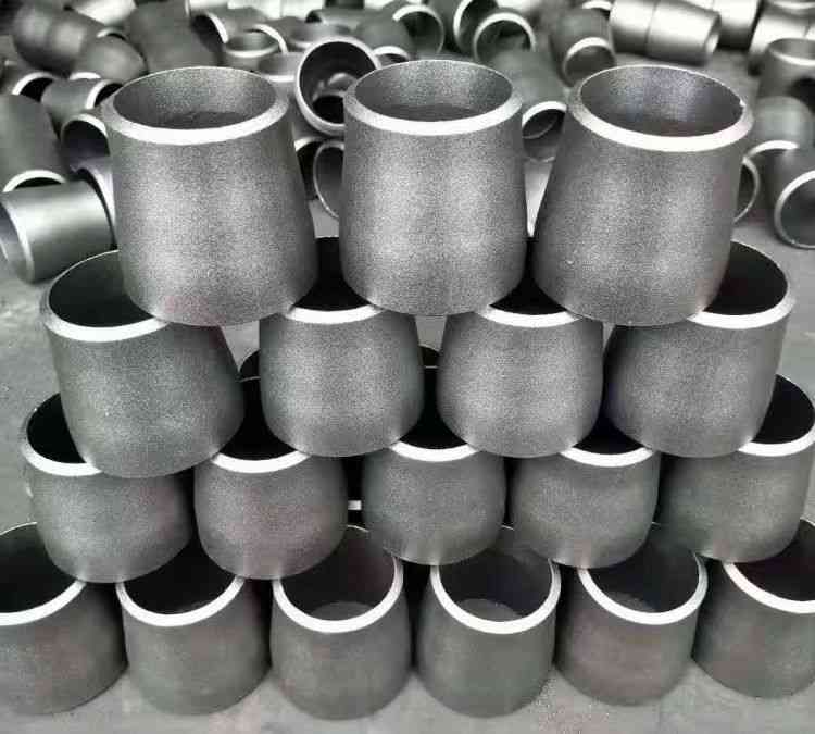
Step 2: Prefabrication and On-site Forming of Tees and Elbows
In accordance with ASTM C450 code, prefabricated insulation covers provide dimension fabrication tables for pipe fitting insulation layers under pressure ranging from 150 to 1500 psi, applicable to tees, elbows, flanges and other fittings.
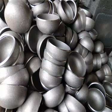
For elbows, tubular insulation materials can be cut into wedge blocks according to the radian and angle of the pipe for close fitting. The common practice is to adopt a “fish-shaped” cutting method: cut insulation segments radially to cover the elbow, with longitudinal joints facing downward to prevent rainwater infiltration.
Industry empirical data: The nominal thickness of insulation layers for elbows shall be the same as that of straight pipe sections. Longitudinal joints of adjacent segmented sections must be staggered with a stagger interval of no less than 200 mm to avoid thermal bridge effect.
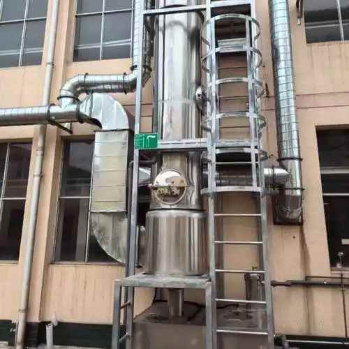
Step 3: Fixation and Cladding
Fix the segmented insulation onto pipe fittings with binding wire, with the center spacing of wire no more than 9 inches (approximately 229 mm). Both ends shall be tightened and embedded into the insulation layer to prevent disengagement.
For marine areas with severe vibration such as engine room exhaust pipelines, stainless steel cable ties or special hook clamps are recommended for additional fixation to prevent loosening. Circumferential and longitudinal joints between outermost claddings must be overlapped and pressed in a staggered manner, and all gaps shall be sealed with butyl aluminum foil tape.
Common Problems and Solutions
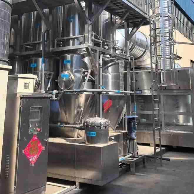
Problem 1: How to inspect hidden hazards at bolt joints of marine insulated pipelines
For piping systems below the ship’s waterline, bolted connections under the insulation layer are prone to concealed corrosion due to long-term exposure to humid conditions.
The solution is to install insulation interlayer leakage monitoring joints, which allow engineers to perform air extraction or pressure charging tests on the cavity under the cladding. Failure to maintain pressure indicates damaged sealing, requiring timely disassembly, inspection and maintenance.
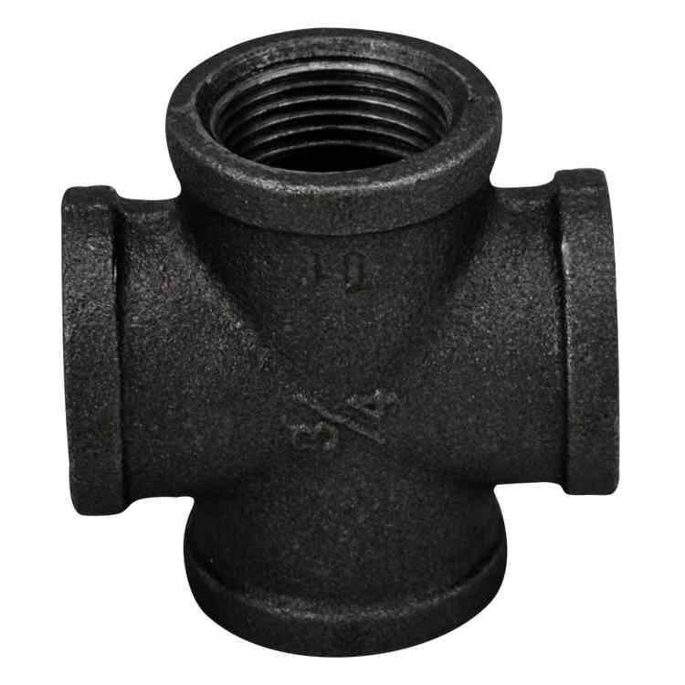
Problem 2: Standardized insulation treatment at supports and hangers of marine pipe tees
Steam traps or fixed Trunnion supports are usually arranged near tees. For steel pipe supports, ISO 24200:2022 standard specifies the design temperature range of supporting components from -46℃ to 200℃. Lug-type supports welded to the main pipe must reserve sufficient expansion allowance.
In actual construction, manufacturers thin the insulation layer at supporting parts and install reinforced arc-shaped protective steel plates complying with MSS SP-58 specifications. This avoids overall thermal efficiency loss caused by heat conduction of supports and prevents support feet from piercing the cladding surface.