Reducing Elbow in a Horizontal Pipe
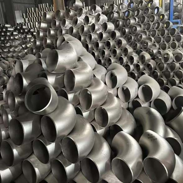
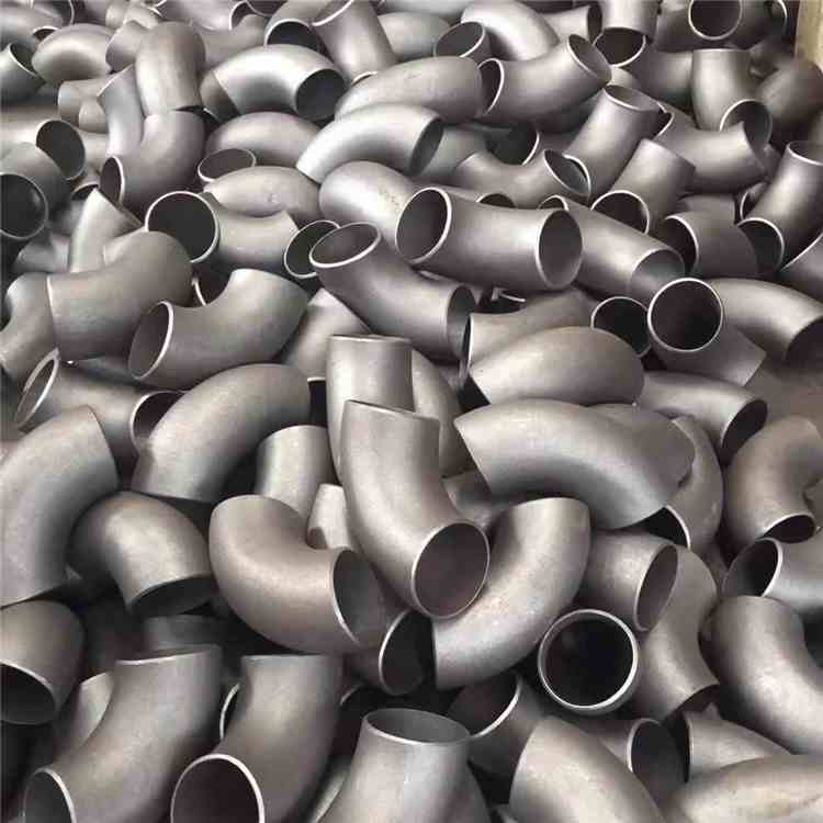
In industrial piping systems, reducing elbow pipe fittings stand out as one of the most efficient solutions when fluid needs to change flow direction horizontally while reducing pipe diameter simultaneously.
This special pipe fitting integrates the direction-changing function of a standard elbow with the reducing function into a single unit, effectively cutting down the number of welds and saving installation space.
This article analyzes the key design points of a reducing elbow in horizontal pipelines from a fluid mechanics perspective, and cites relevant parameters specified in ASME B16.9 and European EN 10253-2 standards, enabling engineers to make more reliable selection decisions.
Why Focus on Reducing Elbows in Horizontal Pipes?
Unlike vertical risers, fluid inside horizontal pipelines is affected by both gravity and inertial force. When installing a reducing elbow in a horizontal pipe, the flow velocity distribution on the inner and outer sides will suffer obvious distortion.
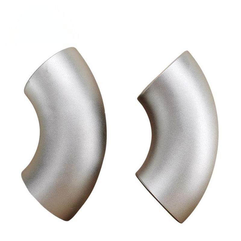
Taking the common 45 deg reducing elbow black pipe as an example, when arranged horizontally, the small-diameter outlet will increase the intensity of secondary flow by approximately 30%~45% compared with standard elbows of the same specification (based on CFD simulation data at Reynolds number Re=1×10⁵).
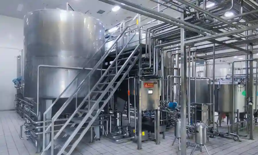
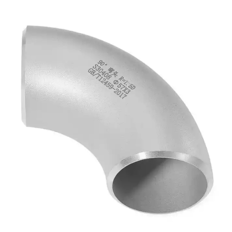
Such secondary flow will aggravate the erosion risk of downstream pipe fittings. Therefore, in Food & Pharmaceutical sanitary piping systems, designers tend to prioritize reducing elbows with a large curvature radius (R=1.5D or 3.0D) to reduce the impact of shear stress on sensitive media such as cell culture fluid and high-purity raw materials.
Key Design Parameters & Industrial Data
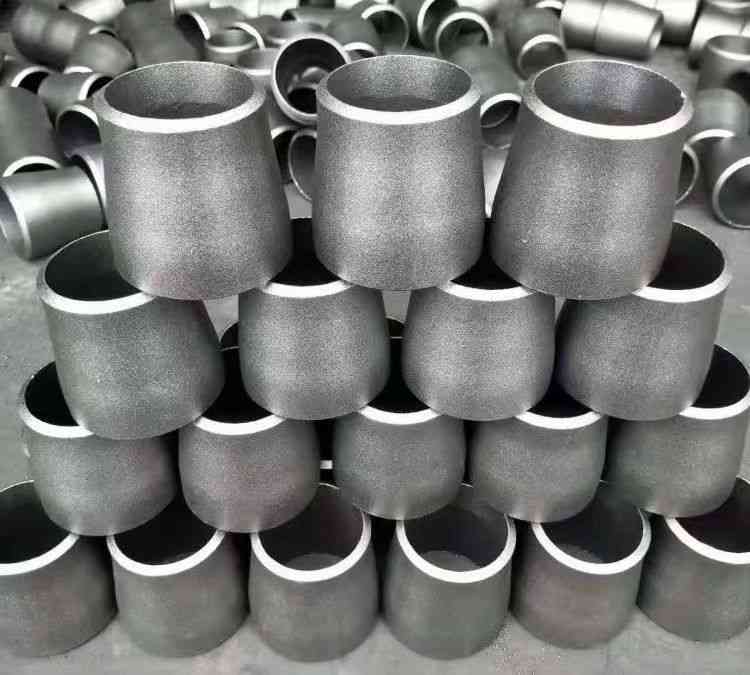
In accordance with MSS SP-79 (Standard for Forged Reducing Elbows), qualified reducing elbow pipe fittings must meet the following geometric specifications:
The taper angle of the reducing section shall not exceed 30°, with a recommended range of 20°~25° to avoid flow separation.
The eccentricity of the outlet end shall be strictly controlled for horizontal pipeline installation. For black pipe reducing elbow applied to non-corrosive fluids such as compressed air and low-pressure steam, the allowable eccentricity tolerance is ±1.6mm; for sanitary-grade applications (e.g., 316L stainless steel polished fittings), the eccentricity tolerance shall be narrowed to ±0.5mm.
The pressure loss coefficient (K value) is the core parameter for model selection. Experiments show that under the same flow rate (taking small-size 1/2″ black pipe elbows as an example), the K value of an integrated reducing elbow is 12%~18% lower than the combined structure of standard elbow plus concentric reducer. This advantage comes from the integrated structure that eliminates additional eddy current caused by intermediate welds.
Specifically, for auto pipe reducing elbow (high-precision reducing elbows matched with automatic welding machines), the inner wall surface roughness can be controlled below Ra 0.4μm. This delays the critical Reynolds number to after Re=2.5×10⁵ and reduces the pressure fluctuation amplitude in the laminar transition zone by around 25%.
Practical Recommendations for Materials & Processes
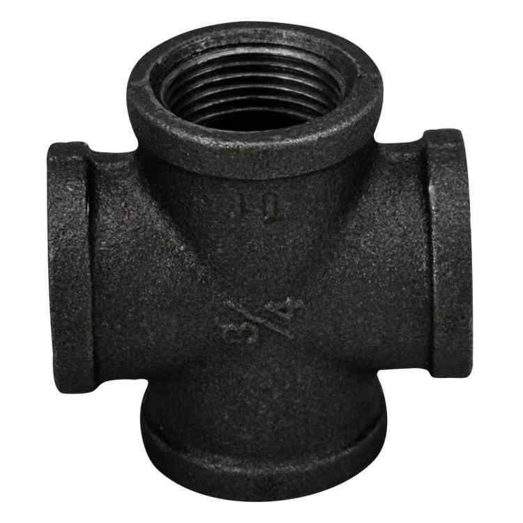
For carbon steel applications, black pipe reducing elbow is generally manufactured from ASTM A234 WPB material, suitable for operating temperatures ranging from -29°C to 427°C. It should be noted that the surface scale of black pipe fittings will increase the fluid friction coefficient by about 8%~10% compared with galvanized or passivated surfaces, making them not recommended for high-purity media in Food & Pharmaceutical industries.
Nevertheless, 1/2″ black pipe elbows are still widely used in utility pipelines of food factories, such as cooling circulating water and steam tracing systems, due to their prominent cost advantage and no direct contact with products.
For pharmaceutical process pipelines requiring zero dead space throughout the flow path, designers prefer electropolished stainless steel auto pipe reducing elbow with orbital automatic welding connection.
The inner contour of such elbows is verified via 3D laser scanning to ensure no sharp corners or steps exist in the reducing transition zone, since any step larger than 0.5mm may become a breeding ground for microorganisms.
In addition, for horizontal installation, it is recommended to place the offset of the reducing section at the top of the pipe (top flat type), which facilitates air exhaust and complete drainage of CIP cleaning fluid.
Conclusion
Whether it is ordinary 45 deg reducing elbow black pipe used in fuel pipelines or high-precision reducing elbow pipe fittings applied in biopharmaceutical reactors, understanding the flow characteristics of reducing elbows in horizontal pipes is the prerequisite for reliable system design.
Complying with ASME BPE and ISO 2851 standards, AIFN Metal Technology supplies a full range of reducing elbows from 1/2″ to 16″. We can also provide third-party flow resistance test reports including K values and pressure drop curves, helping your piping system achieve optimal energy efficiency.