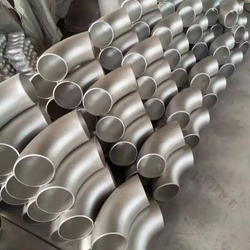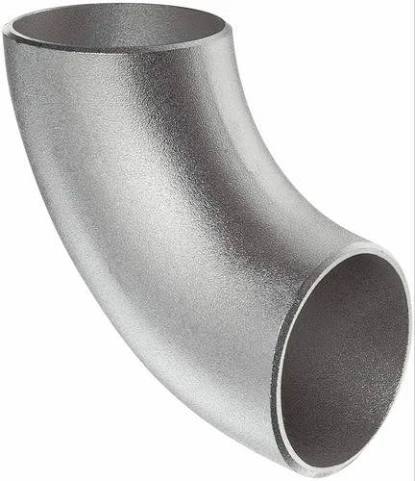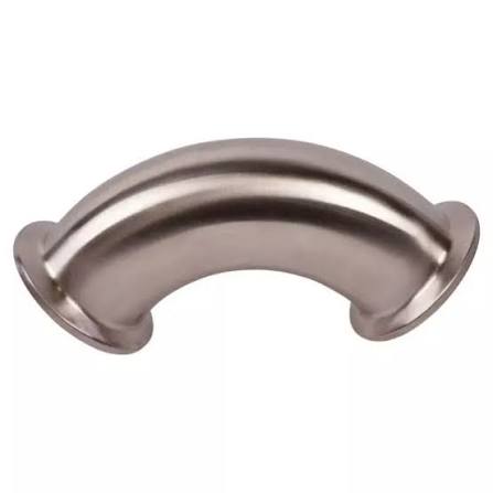
Butt Weld Elbow Testing: A Key Procedure for Ensuring Piping System Integrity
✔️In the oil, gas, chemical, and power industries, the weld quality of butt weld elbows directly affects the safe operation of the entire pipeline. Among the various methods, weld bend testing is one of the most reliable ways to verify the plasticity and internal soundness of welded joints.
✔️This article delves into the core technical details and operational specifications of bend testing welds, helping engineers and procurement professionals understand how a standardized bend test welding procedure can be used to select qualified fittings.
I. Why Perform Bend Testing on Butt Weld Elbows?
✔️Unlike simple tensile tests, bend testing forces the weld root or face to undergo maximum tensile deformation by bending the weld specimen to a specific angle (typically 180°). This process effectively reveals planar defects such as lack of fusion, slag inclusions, porosity, and cracks.
✔️For pipelines subject to cyclic loads, the ductility of welded joints is critical – according to ASTM E190, for guided bend tests on aluminum and aluminum alloys, after bending the specimen to 180°, the length of any single crack on the tension surface shall not exceed 3mm.
II. Key Testing Procedures and Parameters (bend test welding procedure)
A rigorous bend test welding procedure should cover sampling, specimen preparation, equipment selection, and acceptance criteria. 🌈Taking ASME Section IX as an example, for carbon steel elbows with a wall thickness greater than 1/4 inch (6.35mm), side-bend tests are typically used. The specific parameters are as follows:
-
Specimen thickness (t): approximately 3/8 inch (10mm), width is 1.5 times the base metal thickness of the elbow.
-
Bending former diameter (D): ratio to specimen thickness D = 4t (i.e., bend diameter is 4 times the thickness).
-
Bend angle: 180° (full bend until the two parallel surfaces contact).
-
Roller support spacing: approximately (D + 2.5t), ensuring no additional impact on the specimen during bending.
During the test, the load is applied at a constant rate (approximately 10mm/min). Any open defect on the tension surface exceeding 1/8 inch (3.2mm) in length, or a crack at the corner longer than 1/4 inch (6.4mm), is considered unacceptable.
III. Defect Analysis During Bend Testing Welds on Butt Weld Elbows
When performing bend testing welds, common failure modes and their root causes include:
-
Microcracks at the weld boundary: Often caused by hydrogen-induced delayed cracking, especially in low-alloy steel elbows. The risk is extremely high if post-weld hydrogen relief treatment (e.g., holding at 250°C for 1 hour) is not performed in time.
-
Tearing at the root notch: Usually caused by excessive welding current or too slow a travel speed leading to overheating, which coarsens the grains in the heat-affected zone (grain size exceeding Grade 2) and dramatically reduces plasticity.
-
Lack of interlayer fusion: Appears as a linear bright line on the tension surface of the bend specimen, requiring confirmation by scanning electron microscopy. Our internal data shows that when the groove angle is less than 30° or the land exceeds 3mm, the incidence of lack of fusion increases by more than 40%.
As an AIFN company with 8 years of elbow manufacturing experience, we randomly extract welded test plates from each batch and strictly perform bend testing in accordance with ISO 5173 (replacing the obsolete ISO 7438). 🌈For example, for a 12.7mm thick 304L stainless steel elbow, we require that after bending the side-bend specimen to 180°, the tension surface shall have no crack exceeding 1.5mm in length – a more stringent requirement than the standard’s 3mm.
IV. Process Control to Improve Bend Performance of Welded Elbows
To ensure that products successfully pass weld bend testing, four key variables must be controlled at the source:
-
Welding Procedure Specification (WPS) : Strictly limit heat input. For carbon steel (e.g., ASTM A234 WPB), line energy should not exceed 45 kJ/in; for stainless steel, it should be kept below 35 kJ/in to prevent carbide precipitation.
-
Groove preparation: Use machined grooves, with land控制在 1/16-1/8 inch (1.6-3.2mm), and root gap kept consistent with the land.
-
Interpass temperature: For low-alloy steel (e.g., WP22), interpass temperature shall not exceed 400°F (205°C); for austenitic stainless steel, keep below 350°F (177°C) to avoid sensitization.
-
Post-weld heat treatment (PWHT) : For elbows with wall thickness greater than 3/4 inch (19mm), stress relief annealing (620-650°C, holding for 1 hour per inch of wall thickness) is required to eliminate residual stress.
📝Conclusion
Understanding and applying a standardized weld bend testing procedure for butt weld elbows is fundamental to ensuring long-term reliable pipeline operation. With the detailed testing parameters, defect patterns, and process control points provided above, engineers can more confidently evaluate fitting quality. 🌈Choosing high-end products that have been validated by rigorous bend testing welds means choosing a quantifiable safety margin – AIFN delivers the certainty behind every test data point.