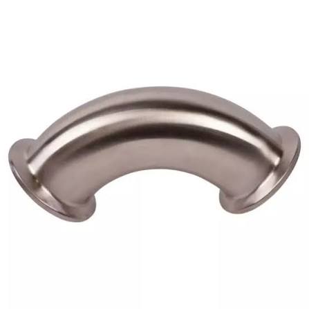
Pipe Bend Radius Calculation | Centerline Radius, Formulas, and Industry Standards
What is CLR (Center-Line Radius)?
✅CLR (Center-Line Radius) is the most fundamental parameter in pipe bending engineering. It refers to the distance from the bending center to the pipe centerline—not the inside radius, nor the outside radius.
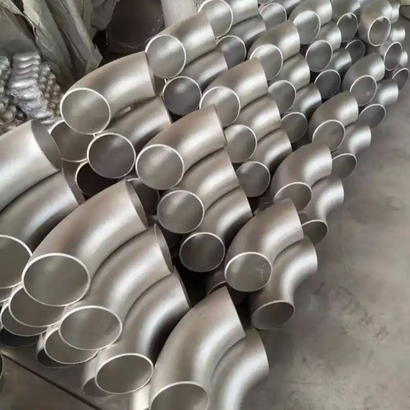
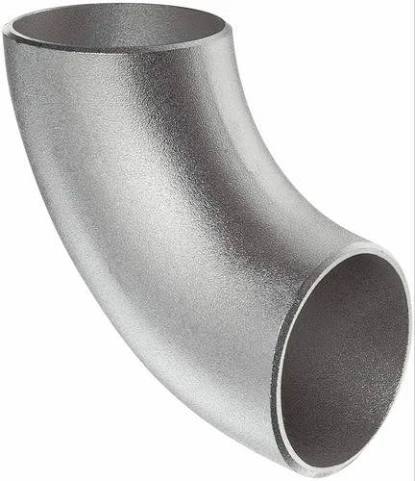
✅In the industry, bends are commonly referred to as 1D, 1.5D, 3D, or 5D, where D represents the nominal pipe size (NPS). CLR = D × multiple. For example, a 1.5D bend has a centerline radius equal to 1.5 times the nominal diameter, which is the baseline parameter for standard long-radius elbows.
✅Many design and fabrication errors occur because the inside radius is confused with CLR. All pipe cutting layouts and stress calculations must use CLR as the reference basis.
Calculation Formulas: How to Calculate a Bend Radius
When designing pipe bends or preparing cutting layouts, “how to calculate a bend radius” is one of the most frequently asked questions. All calculations use the CLR (R) as the baseline input.
1. Standard Elbow CLR
-
Long-radius elbow (LR): R = 1.5 × NPS
-
Short-radius elbow (SR): R = 1.0 × NPS
2. Arc Length (curved pipe length) – used for cutting layout, where θ is the bend angle in degrees:
Arc Length = (π × R × θ) ÷ 180
3. Setback (tangent length) – used for piping layout and isometric drawings:
Setback = R × tan(θ ÷ 2)
Example: 90° bend, CLR = 150 mm
Arc Length = (3.1416 × 150 × 90) ÷ 180 = 235.62 mm
Setback = 150 × tan(45°) = 150 mm
Note: The theoretical minimum bend radius should only be considered as a material limit reference; it cannot be used directly in engineering. The minimum D‑multiple specified in industry standards must always be followed. An excessively small radius will cause outer-wall thinning, inner-wall wrinkling, cross‑section ovality, and create fatigue cracking risks.
Industry Standards & Codes
ASME B31 Series Piping Codes
-
ASME B31.3 Process Piping – For chemical and process piping, this standard specifies minimum bend radius limits for both cold field bends and hot induction bends, and also controls post‑bend ovality and wall‑thinning rates. Cold bending must meet the minimum D‑multiple; hot bending may allow a smaller radius but must be followed by heat treatment to control metallurgy and residual stress. The standard clearly states that factory‑made butt‑welding elbows shall comply with ASME B16.9, while field‑fabricated bends shall follow the bending provisions of B31.3.
-
ASME B31.1 Power Piping – For power plant steam and thermal piping, this code places greater emphasis on thermal stress at high temperatures. Compared to B31.3, power piping typically requires a larger minimum bend radius to reduce stress concentration under elevated‑temperature conditions. After cold bending, an assessment for stress relief is required.
API 5L Oil & Gas Pipeline
✔️For oil and gas transmission pipelines, API 5L distinguishes between factory‑made induction bends and field cold bends. For pipelines subject to pigging operations, the bend D‑multiple must be increased beyond normal process piping parameters to ensure smooth passage of the pig.
✔️Minimum D‑Multiple References by Material (General engineering lower limits; always follow project‑specific standards in practice)
D = nominal outside diameter of pipe
-
Carbon steel – Cold bending: generally ≥3D; for high‑pressure service, ≥5D is recommended. Hot bending may allow a lower multiple but must be followed by heat treatment.
-
Stainless steel – Cold bending: ≥3D is recommended; for thin‑wall stainless steel, ≥4D is suggested to prevent wrinkling and excessive wall thinning. Thin‑wall bends require a mandrel.
-
HDPE plastic pipes – Distinguish between short‑term temporary bending and long‑term permanent installation. For permanent service, the minimum D‑multiple is generally ≥20D. Short‑term construction may allow lower values, but permanently using an overly small bend radius is strictly prohibited to avoid creep deformation and stress cracking.
Cold Bending vs. Hot Bending – Standard Restrictions
📌Cold bending (ambient‑temperature bending) – Includes CNC rotary draw bending and field pipe benders. Since no heating is applied, the material’s elongation limits impose a higher minimum D‑multiple. Thin‑wall pipes must use mandrels and wiper dies to prevent collapse and wrinkling. Cold bending also exhibits springback, so the tooling radius must be compensated to account for springback.
Hot bending (bending after heating) – Localized heating allows smaller bend radii; however, heating temperature and the temperature range must be strictly controlled. After bending, standard heat treatment is required to eliminate residual stress. Stainless steels and alloy pipes must undergo solution annealing or tempering after hot bending; otherwise, their corrosion resistance and mechanical properties will be degraded.