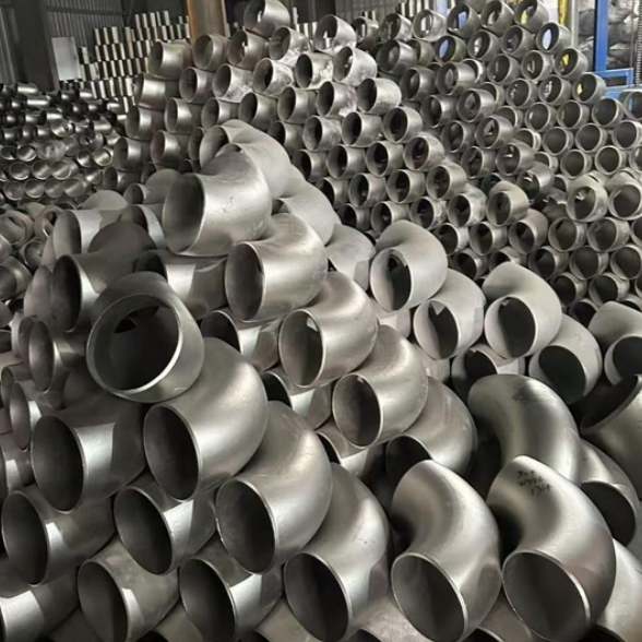
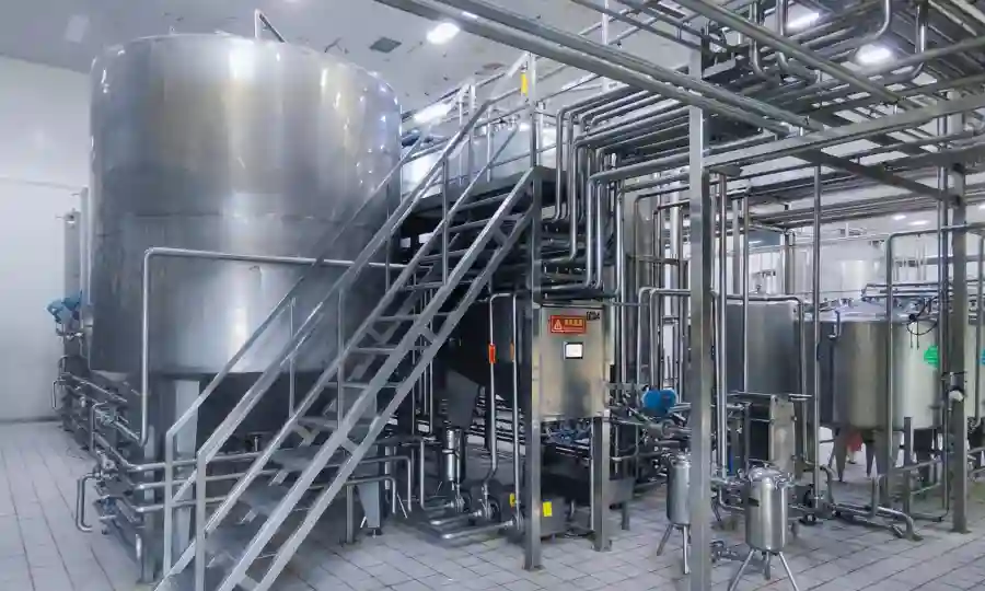
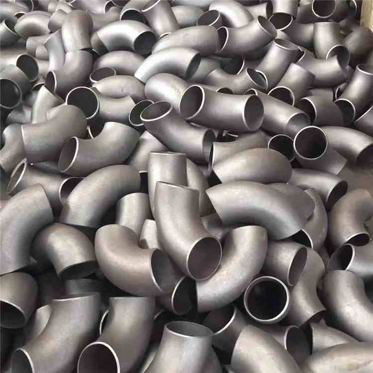
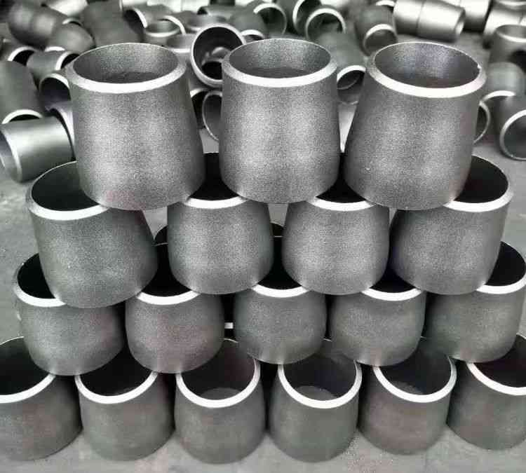
In power industry piping systems, elbows are critical components for changing the flow direction of media. Whether it is the main steam pipeline of thermal power plants, the cooling water circulation system of nuclear power plants, or the gas transmission pipelines of gas-fired power plants, accurate dimension calculation of pipe elbow directly determines the prefabrication precision of pipelines, welding quality, and long-term operational safety of the complete unit.
Based on the ASME B31.1 Power Piping Code, this article introduces practical calculation methods for elbow length.
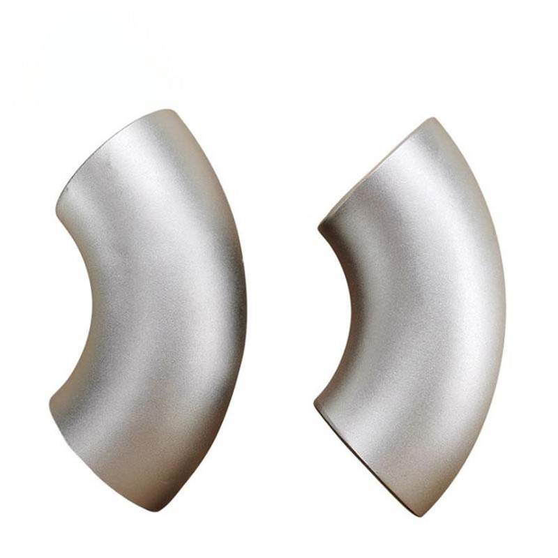
First, it is essential to clarify the basic concept: the center-to-face dimension of a pipe elbow, commonly referred to as “takeoff” in the industry. It is the linear distance from the virtual bending center point of the elbow to the end bevel on both sides, serving as the reference value to be deducted when calculating the cutting length of straight pipe sections.
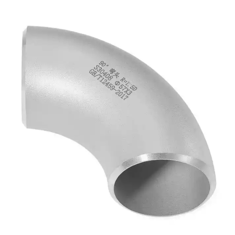
For 90° Long Radius elbows, the most widely used type in power projects, the Center Line Radius is 1.5 times the Nominal Pipe Size (NPS) (R=1.5NPS), which is clearly specified in the ASME B16.9 standard for butt-welding fittings.
Accordingly, a highly practical empirical formula is concluded:
Elbow center-to-face dimension ≈ Nominal Pipe Size (inch) × 38.1 (mm conversion factor).
For example, the theoretical dimension of a NPS 4 90° LR elbow is calculated as 4×38.1=152.4mm, which is consistent with the standard value of 152mm specified in ASME B16.9.
For non-standard angle fittings or spiral hot-bent pipes, a general trigonometric formula shall be adopted:
Elbow Length = Tan (Elbow Angle/2) × Curvature Radius.
Taking the 60° gentle bend commonly used in main steam pipelines as an example, if processed from a standard 90° LR elbow, and the center-to-face dimension of the NPS 4 elbow is 152mm, the actual length is calculated as follows:
Actual Length = Tan(30°) × 152 ≈ 0.5774×152 ≈ 88mm.
This formula is of extensive engineering value in steam piping elbow fabrication and precision pipeline prefabrication.
When modeling in piping stress analysis software, the accuracy of pipe elbow center-to-face dimension calculation directly affects the distribution of end restraint forces and the selection of thermal compensators.
Especially for high-temperature and high-pressure pipelines with design pressure above 8MPa, the ovality deviation of elbow fittings must be controlled within 5%.
Therefore, it is necessary to strictly comply with the ASME B31.1 Code in the calculation phase, which covers the whole process of design, material selection, testing and inspection of piping systems in power generation facilities. Meanwhile, the dimensional tolerance requirements of ASME B16.9 shall be followed, such as the wall thickness negative tolerance not exceeding 12.5%, to ensure that calculated dimensions match the actual product specifications.
Q1: In large-diameter long-distance pipelines of power piping systems, how to solve the problems of uneven wall thickness and processing thinning of pipe elbow?
A: Hot pushing forming technology is the mainstream solution at present. In the production of large-diameter power pipeline fittings, seamless steel pipes are heated to the austenitizing temperature (approximately 850-950℃). With the coordination of the pushing machine core head and annular induction heating coil, the metal undergoes flow flushing and gradual plastic deformation at high temperature, so as to produce seamless pipe elbow with relatively uniform wall thickness.
For high-temperature and high-pressure main steam pipelines under extremely severe working conditions, manufacturers generally select elbows made of creep-resistant alloy steel materials such as WPL6 or P91/92. In the design phase, an additional 20%-30% of the original wall thickness is reserved as wall thickness compensation, ensuring that the minimum wall thickness of thinned areas after push forming still meets the safety requirements of ASME B31.1 specifications.
Q2: During steam piping elbow fabrication, how to avoid potential safety hazards of circulating units caused by accumulated torque generated by thermal expansion and cold contraction of pipe elbow?
A: Optimization shall be carried out from two aspects: spatial arrangement of elbows and cold spring technology.
First, optimize the elbow combination and bent pipe replacement strategy. Within the limited space of four major power pipelines, replace the traditional combination of large curvature radius elbows (R/D=1.5) with segmented connections of 2-3 cold bends with medium bending radius (3≤R/D≤5). This design meets the demand of flow direction conversion while greatly reducing the end thrust of the piping system.
Second, adopt cold spring technology. Before pipeline butt welding, reserve reverse displacement actively at a proportion of 50%-80% of the designed stress, namely the “cold spring gap”. During hot operation, the thermal expansion displacement offsets the cold spring displacement, which effectively reduces the thrust and torque exerted by the pipeline on the interface of rotating machinery (such as turbine inlets and outlets). It fundamentally prevents operational risks including casing deformation, bearing deviation and excessive vibration.