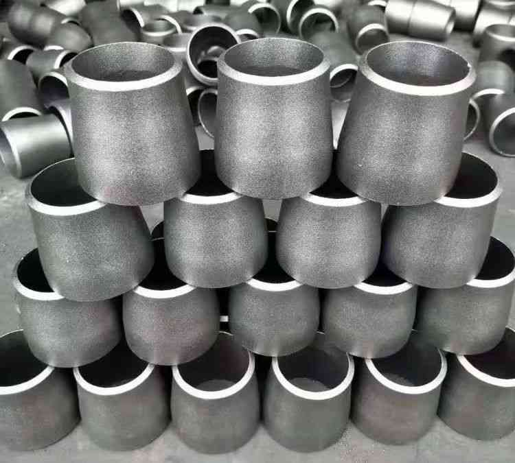
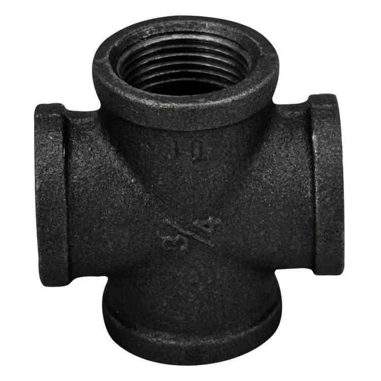
▶️ In pipeline connections, transitioning between different sizes of fittings is a common requirement, and the reducer coupling is the core component addressing this need. Among them, the 3/4″ female to 1/2″ male reducer is widely used in instrumentation lines, pneumatic systems, and low-pressure fluid distribution networks.
▶️ This article will dissect the key parameters of such couplings from a technical perspective and compare them with other typical specifications to assist engineers in making precise selections.
Thread Standard and Fit Accuracy
✔️The majority of industrial reducer couplings employ NPT threads with a taper of 1:16, relying on interference fit of the thread profile to achieve sealing. Taking the 3/4″ female NPT as an example, it has 14 threads per inch, a minor diameter of approximately 0.967 inches (24.6mm), and an effective engagement length of no less than 4 full threads.
✔️The 1/2″ male NPT also has 14 threads per inch, with a major diameter of about 0.840 inches (21.3mm). When tightening the male and female threads, a torque of 20–30 N·m (depending on material) is recommended to ensure sealing without damaging the threads. For high-pressure conditions (≥3000 psi), PTFE tape or liquid sealant can be applied.
Material and Pressure-Temperature Ratings
According to ASME B16.11, the pressure ratings for socket weld and threaded reducer couplings are divided into Class 2000, 3000, and 6000. Common materials include:
-
ASTM A105 (carbon steel): Suitable for -29°C to 427°C, with a working pressure of approximately 25.8 MPa (3740 psi) under Class 3000.
-
ASTM A182 F316 (stainless steel): Resistant to chloride corrosion and performs excellently in petrochemical media, with pressure ratings slightly higher than carbon steel at the same class.
A practical case: In an oil refinery’s instrument air line, a 1 1/2″ to 1 1/4″ reducer coupling was used to transition from a 1.5-inch main pipe to a 1.25-inch branch pipe. The selection of F316 material allowed it to operate continuously for 5 years in a sulfur-containing wet gas environment without thread crevice corrosion.
Comparison of Other Typical Specifications
-
1 1/2″ x 1 1/4″ reducer coupling: Commonly used at pump inlets and outlets for diameter reduction to reduce turbulence. Experimental data shows that concentric reducers are more prone to gas accumulation in horizontal installations compared to eccentric reducers. Therefore, an eccentric flat-on-top (FOT) configuration is recommended for liquid pipelines.
-
3 inch to 2 inch reducer: In high-flow circulating water or crude oil transportation, the 3″ to 2″ reducer reduces pressure drop caused by sudden velocity changes. According to the Darcy-Weisbach formula, at a flow rate of 200 GPM, the velocity in the 3″ section is about 2.2 m/s, which increases to 4.9 m/s after the sudden contraction to 2″. The local resistance coefficient ζ is approximately 0.35. Selecting an appropriate gradual length (typically ≥1.5 times the diameter difference) effectively mitigates vortex formation.
Special Requirements in the Petroleum and Chemical Sectors
✔️In the two industries mentioned above, the media in pipelines often exhibit high temperature, high pressure, or strong corrosive characteristics. For example, in a hydrogenation unit’s low-pressure flushing system, a 3″ main pipe needs to be reduced to a 2″ injection point. Using an ordinary 3″ to 2″ reducer may cause leakage due to insufficient wall thickness.
✔️All reducer couplings provided by AIFN undergo shell and hydrostatic tests in accordance with API 598, with carbon steel products additionally subjected to -46°C impact testing. It is worth noting that in refinery analyzer shelters, the 3/4″ female to 1/2″ male reducer is extensively used for connections between sampling valves and instruments — this seemingly small transition directly determines the pressure sampling stability of online chromatographs.
📝Conclusion
✔️From 3/4″ to 3″ reducing specifications, each requires comprehensive consideration of thread fit, pressure rating, corrosion allowance, and installation space. Mastering these technical details not only extends the service life of fittings but also enhances the safety factor of the entire fluid system.
✔️If you are selecting suitable reducer couplings for projects in the Petroleum & Chemical sector, please refer to AIFN’s product data sheet. We provide complete traceable documentation ranging from material certifications to dimensional reports.