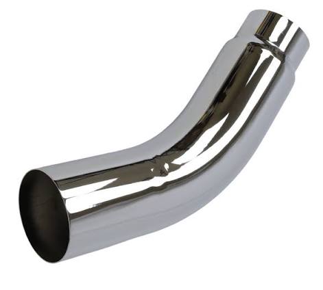
Stainless Steel Exhaust Elbows for Welded Tube Fit-Up
Stainless steel exhaust elbows for fabricated exhaust runs. Compare Tube OD, bend angle, CLR, wall thickness, leg length, V-band fit-up, and finish.
Description
stainless steel exhaust elbows are used to change direction in exhaust pipes, downpipes, and custom exhaust assemblies. This page focuses on the welded fit-up of thin-wall Tube and does not treat the product as an ASME pressure-piping elbow.
Exhaust Elbow Fit-Up Data Card
| Item | Requirement |
|---|---|
| Tube OD | Use the actual outside diameter rather than NPS or a nominal hose size |
| Bend Angle | 45°, 90° or the angle shown on the drawing |
| CLR | Centerline Radius determining packaging space and bend compactness |
| Wall Thickness | Specify in mm, inch, or Gauge rather than inferring it from outside diameter |
| Leg Length | Both straight-end lengths determine cutting, clamping, and welding allowance |
| End Fit-Up | Butt Weld, V-band, Flange, or Slip Joint confirmed by drawing |
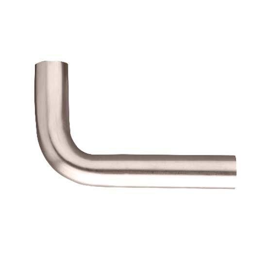
90 degree stainless steel exhaust elbow
A 90° elbow should specify Tube OD, CLR, and the Leg Length at both ends. Elbows with the same outside diameter may use different CLR values, producing significantly different installation envelopes and clearances from the vehicle body, equipment, or supports. The purchasing drawing should identify the bend plane to prevent incorrect outlet rotation during assembly.
3″ stainless steel exhaust elbow
The 3 inch size should normally be identified as a 3.000 inch Tube OD and should not be assumed to equal 3 inch NPS. Wall thickness, material, surface condition, and the actual outside diameter of the mating straight tube should also be confirmed. If one end requires a V-band or expanded connection, the fitting series and final welded overall length should be stated separately.
stainless steel 45 degree exhaust elbow
A 45° elbow can form a gradual offset. When two 45° elbows are combined with a straight tube, the center offset, Clocking of both elbows, and intermediate straight length should also be provided. Angle and outside diameter alone do not ensure assembly alignment. After cutting, sufficient straight length should remain for fixture location and circumferential weld fit-up.
stainless steel exhaust pipe elbow
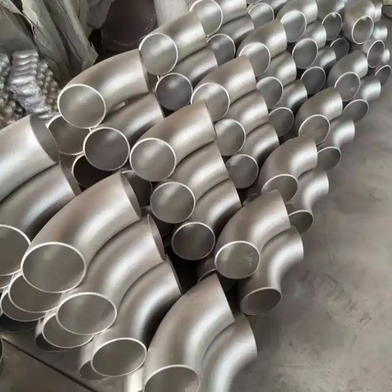
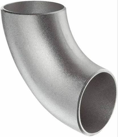
An exhaust elbow may be manufactured as a Mandrel Bend, Weld El, or segmented fabricated elbow. These forms can differ in CLR, wall thickness, and weld count. When a supplier proposes a substitution, weight, flow path, installation space, and welding procedure should be reviewed again. Exhaust temperature, vibration, supports, and condensate low points also require system-level consideration.
stainless steel marine exhaust elbows
Marine Exhaust may include cooling-water injection, exhaust hose, waterlocks, and backflow prevention and should not be treated as an ordinary Dry Exhaust elbow. The inquiry should state whether the system is Wet or Dry and should identify inlet and outlet materials, hose or welded connections, installation height, and seawater environment. The stainless steel material name alone does not prove suitability for a complete marine exhaust system.
Exhaust Elbow Cutting and Trial-Fit Sequence
First use the actual mating straight tube to check Slip Fit or Butt Fit clearance, then mark the bend plane and cutting datum on the elbow. After cutting, remove burrs and perform a dry fit to check overall assembly length, support locations, and clearance from adjacent components. Fix Clocking before final welding. Polished, brushed, and mill surfaces should also have separate post-weld cleaning requirements.
stainless steel exhaust elbows Specifications
| Parameter | Specification |
|---|---|
| Product Name | Stainless Steel Exhaust Elbows |
| Product Type | 45 or 90 Degree Exhaust Tube Elbow |
| Manufacturing Form | Mandrel Bend, Weld El or fabricated elbow, subject to drawing |
| Tube Size | Actual Tube OD specified in inch or mm |
| Wall Thickness | Specified by mm, inch or Gauge |
| Bend Angle | 45°, 90° or project drawing |
| CLR | Centerline Radius confirmed by product drawing |
| Leg Length | Both end lengths specified for cutting and fit-up |
| Material | 304 Stainless Steel common manufacturer configuration; other grades subject to order confirmation |
| End Fit-Up | Butt Weld, V-band, flange or slip joint, subject to assembly drawing |
| Surface Finish | Brushed, polished or mill finish, subject to order confirmation |
| Service Data | Exhaust temperature, vibration, support, dry or wet service and condensate conditions required |
| Inspection Items | Visual, Tube OD, wall thickness, angle, CLR, leg length, surface and fit-up review |
| Customization Boundary | OD, angle, CLR, wall thickness, leg length, end fit-up and finish, subject to technical review |
Frequently Asked Questions (FAQ)
1. Does 3 inch in a 3″ exhaust elbow always refer to outside diameter?
Not necessarily. Search terms may mix Tube OD, NPS, or hose size. Welded exhaust tubing should normally be specified by actual outside diameter and wall thickness and confirmed against the mating straight tube or connection drawing. The words 3 inch alone are not enough to establish the fit-up dimensions of a 3″ stainless steel exhaust elbow.
2. Can a marine wet-exhaust elbow directly replace an ordinary exhaust elbow?
No. Wet Exhaust also involves cooling water, hose connections, waterlocks, backflow prevention, and seawater corrosion conditions. stainless steel marine exhaust elbows should be reviewed as part of the complete marine exhaust system and should not replace Dry Exhaust parts only on the basis of angle and material.
More Products