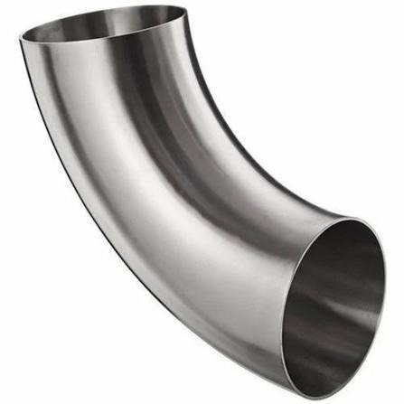
30 Degree Stainless Steel Elbow Installation Notes
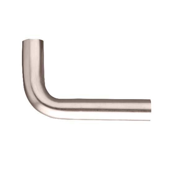
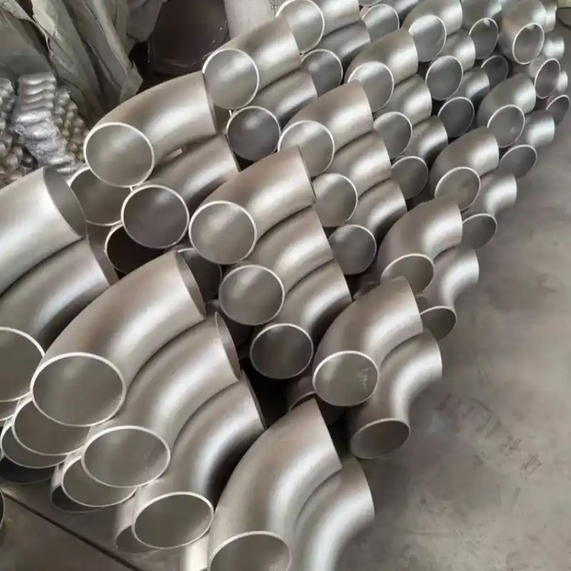
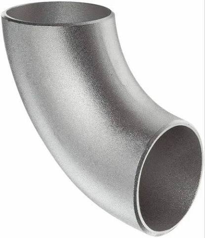
30 degree stainless steel elbow for equipment inlets. Confirm inlet orientation, center-to-end dimensions, wall thickness, weld access and drawing details.
Description
A 30 degree stainless steel elbow is often used at equipment inlets, branch offsets, and pipe routes where the turn must be controlled. It can preserve a more continuous layout direction than a right-angle turn, but suitability still depends on inlet coordinates, equipment flange or nozzle direction, and surrounding maintenance space. The product information should focus on interface fit rather than describing a generic elbow.
Check Coordinates Before the Product Name
At an equipment connection, angle is only one field. Confirm center-to-end dimension, both elevations, bend plane, pipe size, wall thickness, and end configuration. If the drawing is controlled by northing, elevation, or coordinates, give those data to the supplier and request a returned dimensional drawing. This prevents a part from arriving with the correct angle but the wrong direction or end position.
Field Constraints for Welding and Material
A butt-weld end needs room for the welding torch, clamps, and measurement. The wall-thickness transition must also match the straight pipe. Select the grade against the medium, temperature, and project specification rather than ordering from the casual name “304 stainless steel” or “316 stainless steel.” If the equipment requires cleaning, pickling and passivation, or special packaging, list those items separately so the elbow is not confused with a standard industrial part.
Geometric Boundary at the Equipment Inlet
For an equipment inlet, first check nozzle coordinates, inlet direction, center elevation, and end distance before deciding whether the angle works. Also confirm the bend plane, flange or weld end, maintenance clearance, and nearby supports. “30 degree” alone cannot prove that the elbow will connect to the equipment.
Installation Sequence and Receiving
Before installation, compare the equipment drawing and piping layout, then check the elbow and straight pipe for outside diameter, wall thickness, grade, and welding method. Leave welding and inspection space during fit-up instead of twisting the elbow to correct the direction. On receipt, check angle, center-to-end dimension, end protection, and batch identification; send any dimensional change back to the drawing.
If insulation, valves, or removal space are near the equipment inlet, include those boundaries in the layout. This helps identify during procurement when an end can connect dimensionally but leaves insufficient operating space.
At an equipment inlet, end direction and center elevation often create more rework than the angle name. Use the equipment connection drawing, piping class, and elbow dimensional drawing on the same coordinate basis. During dry fit-up, confirm overall length, center-to-end dimension, and nearby valve space before tack welding.
If the two ends use different configurations or require field welding, list each end separately in the quotation. Installation and inspection access must remain on the layout; an angle-correct part with the wrong bend plane is still not ready for installation and must return to the drawing for resolution.
If insulation, valves, or instruments are present, include the finished-surface dimensions in the returned drawing. Use the equipment coordinates and pipe centerline during field confirmation; dry-fit before welding so direction and operating-space problems are found early.
The dimensional drawing should show the equipment flange face, pipe centerline, and elbow end rather than only an overall length. This supports quotation and lets the site check angle, elevation, and end condition before tack welding.
Also check insulation thickness, flange-bolt space, and the maintenance passage around the equipment inlet so the pipe does not need to be rearranged after the finished surfaces are installed.
Equipment-Inlet Installation Sequence
- Check the equipment nozzle drawing and piping class first, then confirm the 30° elbow orientation.
- During dry fit-up, confirm center-to-end, elevation, and bend plane before tack welding.
- Check both outside diameters, wall thicknesses, and bevels against the straight pipe and welding procedure.
- Keep access for welding and inspection so the elbow is not placed too close to the equipment.
- Archive the dimensional drawing, material documents, and field confirmation record together.
Product Parameters
| Parameter | Review Specification |
|---|---|
| Angle | 30°; tolerance is subject to the product drawing or project standard. |
| Interface direction | Confirm against the equipment nozzle drawing, elevation, and bend plane. |
| Center-to-end | Use the supplier dimensional drawing and project coordinates. |
| Nominal size / outside diameter | Confirm against the matching straight pipe and piping class. |
| Wall thickness / Schedule | Confirm against the design specification. |
| Material | Project-specified grade, standard, and certificate requirements. |
| Ends | Butt-weld or another specified interface; confirm end preparation. |
| Surface / cleanliness | Industrial or clean-service requirements are subject to order. |
| Inspection documents | Dimensional, angle, appearance, and material documents are subject to project requirements. |
Frequently Asked Questions
Can a 30 degree elbow directly replace a 45 degree elbow at an equipment inlet?
No. The angle, end position, and pipe coordinates all change. Recheck the equipment drawing and site space, and obtain engineering confirmation before substitution.
Why should an equipment-inlet elbow be supplied with a dimensional drawing?
Because the hardest problems to correct after delivery are usually an incorrect end position, bend plane, or center-to-end dimension. A drawing can expose these issues before the order is placed.
More Products